Setup and Adjustment
Setting up and adjusting the machine to compute reliably takes a lot of time and attention to detail, but once adjusted, the machine should perform reliably. After initial construction it's likely that the machine will lock up on attempting
to turn the main crank. First, note that the crank should only ever be turned counter clockwise as viewed from the top (except for a few degrees clockwise when investigating the source of a jam). During the adjustment process, whenever any resistance is encountered in turning the crank, stop and investigate where the problem is and either correct it if the problem is obvious, or if it's not, disconnect parts of the drive so as to be able to isolate the location of the problem.
| The
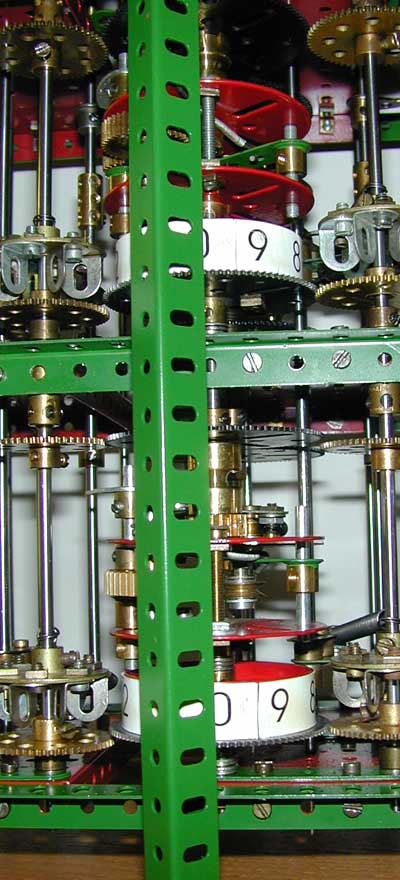
first step in setting up is to align all the digit readout cages. In
Babbage's original machines he was concerned about evening out the
loading on the
mechanism and staggered the operation so that not all digits
were
added at exactly the same time. However, for this small scale model the
number of digits is small enough for this not to be an issue so
instead,
all nine digit readout cages should be aligned to the same
position.
This is most easily done using a 24½" angle girder held
vertically
in front of each difference axis as shown in the picture to the right.
Choose
some point on the readout cage, such as one of the bolts, and align
each
cage to the same position relative to the girder. Be sure as each cage
is
aligned it is tightly secured to the axis so there can be no slipping. Next, for each readout cage, adjust the bolt which engages with the pin on the digit wheel. When the mechanism is in the disengaged position, the bolt head should pass over the threaded pin with minimal clearance. Manually engage the pawl in the readout cage and observe it disengage as the readout cage rotates. If the bolt is too far in, the head may drag the digit wheel round rather than disengaging. If it's not close enough, then the mechanism may not fully disengage as the bolt passes the threaded pin. |
|
| Once
the readout mechanism is disengaging smoothly, the next step is to
align
the mechanism on the bolting axes. These axes turn at one quarter the
rate
of the difference axes, so once every fourth turn of the crank, the
spring
loaded ½" pulley on the bolting assembly needs to engage with
the
upper pawl on the readout cage and cause the mechanism to engage. Odd
and
even differences are added in turn, so the bolting assemblies on the
first
and third difference axes should be aligned to the same position, and
those
on the second difference axis should be set at 180º to those on
the
first and third difference axes. This can easily be accomplished
by
turning the crank two full turns after aligning the first and third
differences,
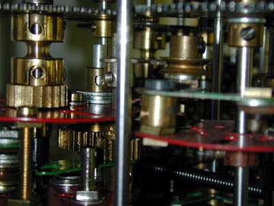
then set the assemblies on the second difference similarly. The picture
to
the right shows a close up of the pulley encountering the pawl on one
of
the assemblies. The
pawl needs to be positioned so that (assuming the digit wheel is not
currently reading zero) as the bolting assembly passes by, the readout
mechanism is cleanly engaged. If the pawl is set too far out the pulley
will be deflected. If it is too far in the readout mechanism may not
fully engage. |
 |
At this point we are ready to start testing the addition mechanism and making the fine adjustments. Before proceeding it is best here to disable the carry mechanism by ensuring the 2" rods on the carry axes are not
engaging the pulleys on the face plate assemblies. If carries are trying to happen it makes it very confusing to determine if the digit addition is happening correctly.
Set all the digit wheels to zero (always turn them in the direction of increasing numbers). Now when the crank is turned there should be no activity since each digit wheel is in the position where the readout mechanism should not engage. Investigate all the cases where a readout is happening and adjust as above to prevent this. There should only be very slight resistance to the crank each time the bolting assemblies engage the pawls on the readout cages.
Turn the crank at the rate of one turn every one to two seconds. Once you can turn the crank for at least 100 turns with no change to any digit wheel happening, move on.
Next, set the lowest digit wheel on the first difference axis to the value 1. Now, for every four turns of the crank, the lowest digit wheel on the result axis should advance by one position. If this does not happen reliably some fine adjustment is needed. Look to see where the pawl lands relative to the teeth of the ratchet wheel as the mechanism engages. It should be as close as possible to the next tooth so that there is as little lost motion as possible before the ratchet wheel starts to turn. Rotate the ratchet wheel very slightly in the socket coupling to make this be the case. It may also be necessary to adjust the resting position of the digit wheel very slightly to control when the bolt and threaded pin disengage the mechanism. Once you have this working reliably say ten or twenty times in a row without error, try advancing the digit wheel on the first difference axis to 2. Now with each operation, the wheel on the result axis should step on by two positions. Test out each value on the digit wheel and check the correct number of positions is advanced on the result wheel. You will probably find some cases that advance either one two few or one two many. Repeat the fine adjustment of the engage/disengage action as before to correct. Of course if you do have to make a further correction, go back and check that the previously working cases still are. If you cannot get all 10 positions of the wheel to cause the correct advancement of the result wheel, check the positioning of the angle brackets on the detent wheel to make sure they are uniform. If not the digit wheel may be slightly out of position for some values (and because of the 5:3 ratio to the detent wheel the failing values which change from rotation to rotation!)
Once you have this first digit working, proceed the same way with each of the remaining digits of the first difference axis. Once all four digits of the first difference axis add correctly, follow the same procedure for the second difference axis, and then finally the third difference.
| If
you have got this far, congratulations! Now we can start work on the
carry mechanism. The first thing to adjust is the position of each of
the carry trip 2½" gears. When a digit wheel passes from 9
to 0, the angle bracket on the gear must trip
the pawl to arm the carry mechanism for the next digit. When the digit
wheel
is at 9 there should be about 1/8" space between the angle
bracket
and the pawl. Too little space and it's possible an overshoot on the 8
to 9 transition will trip it prematurely. Too far away, and the
9
to 0 transition may not. The carry mechanism can easily be
reset manually
after it has tripped as you work on this adjustment. You may need to
come
back and fine tune this once carries are basically working. The upper
pawl
on the carry trip rod will need to be set so that the carry assembly is
released
with the minimum amount of motion of the pawl. |
The carry axes rotate at one half the rate of the digit wheels. Although a carry only needs to occur every four rotations on any given axis, if the carry axes were only to rotate at one fourth the rate, then the reset of the carry assembly by the 2" rod would be too slow to allow all the carries on one axis to complete before the next addition starts. On every second revolution of the carry axes, there should be no carry assemblies tripped, so even though the 2" rods pass the carry assembly on this revolution no action should occur. The 2" rods need to be set so that they just cause they carry assembly to reset, with minimal contact with the pulley in the case the carry has not been tripped.
In each cage, the 2" carry arms should be aligned to the same rotational position for all three carry axes so that carries happen at the same point in the cycle independent of which axis is involved. Proceeding up from the 10's cage to the 100's cage, the arms need to be set about 60º later than for the 10's cage, and in the 1000's cage a further 60º later. This is so that carries can propagate from one digit position to the next and if as a result the digit wheel passes from 9 to 0, a further carry can be set for the next cage above before the carry arm comes by to reset it.
On the whole, the carry mechanism should be much easier to adjust than the digit readout. However, a similar fine adjustment may be needed to the position of the ratchet wheels so that the carry mechanism reliably advances the digit wheel by exactly one position when the carry is reset. Ensure that when the carry assembly is tripped, the pawl lands just beyond a tooth on the ratchet wheel so there is no lost motion during the reset operation.
Framework
Arrangement of axes and drive system
Decimal digit storage
Digit readout and addition
Carry detection and propagation
> Setup and adjustment
Operation
Parts List
Last modified: 16 July 2004 If you experience any problems with this site, please contact the webmaster |
©
2003, 2004 Tim Robinson |