Carry Detection and Propagation
(Eight of each assembly are required)Addition in the difference engine proceeds in two phases. In the first phase, numbers are added digit by digit, and then in the second phase, any carries that were generated in the first phase are added to the result. The pictures below show the assemblies needed to accomplish the detection and subsequent propagation of carries. The axes which carry the digit wheels rotate four revolutions per cycle of the machine. During the phase where digit by digit addition is taking place, if the output digit wheel passes from 9 to 0 then a carry must occur to the next higher digit in the same column.
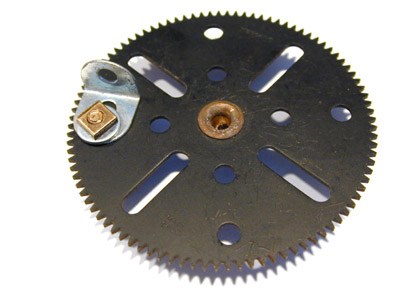 |
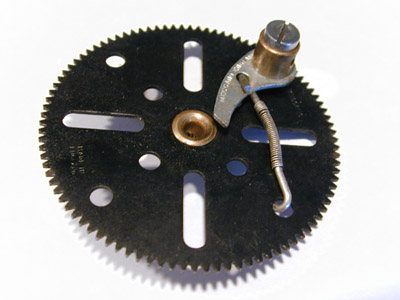
Detection
of the carry is very simple. A 2½" gear wheel mounted freely on
the bolting axis engages with the upper 2½" gear of the digit
assembly. This gear carries an angle bracket mounted by its slotted
hole to one of the outer round holes of the gear. Be careful when
positioning this to make sure that the teeth of the gear fully project
beyond the angle bracket. When the digit wheel advances from 9 to 0, the angle bracket trips a pawl which releases a spring loaded carry assembly. In the subsequent carry phase of the cycle this assembly will be reset, resulting in the addition of one more count to the next higher digit wheel. |
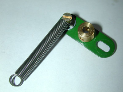
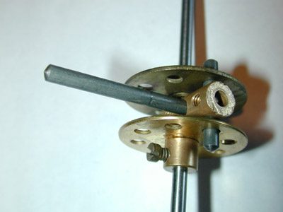
| To
the right is the simple assembly which mounts on the rod carrying the
trip pawl. The tension spring is attached by a 3/8" bolt. After
assembly, the other end of the spring fits over a rod in the rearmost
row of holes in the flanged plates of the framework and provides the
tension to hold the carry trip pawl in place. A stop is provided by a
short threaded pin also mounted in the flanged plate of the frame. |
 |
 |
 |
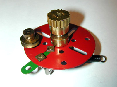
| The
ratchet wheel will engage with a pawl mounted on a 2½" gear
wheel by a pivot bolt. A small spring to hold the pawl in engagement is
formed from about ½" of spring cord and two hooks for spring
cord. In operation, when a carry is detected the spring loaded carry
assembly is released and rotates until the narrow strip hits a stop,
allowing the pawl to pass over two teeth on the ratchet wheel. In the
carry propagation phase when the assembly is reset, the gear will
be carried through 1/10th of a rotation. The gear engages with the
2½" gear of the digit wheel, thus advancing it by one count. |
 |
 |
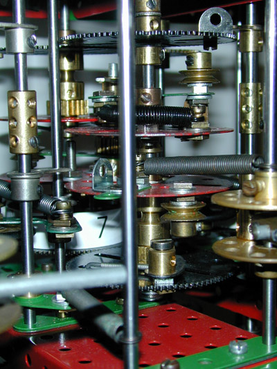
The carry assembly is reset by an
arm rotating on the rearmost axis, the carry axis. The arm is simply a
2" rod mounted in a coupling. The length of the rod protruding needs to
be carefully adjusted for correct operation of the carry mechanism. as
it rotates the rod will engage with the pulley on the carry assembly if
set, bringing
it back to the reset position and advancing the digit wheel one count. A single grub screw in the coupling is insufficient to ensure no slipping under the load of operation. To overcome this problem, the coupling is sandwiched between two bush wheels with a 1" rod locking all three components together. Now the load can be carried by the set screws in the bosses of the bush wheels. The bush wheels are bolted together by a 3/4" bolt with a short coupling as spacer in the hole opposite the 1" rod. |
 |
 |
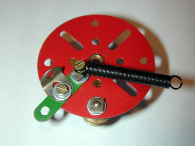
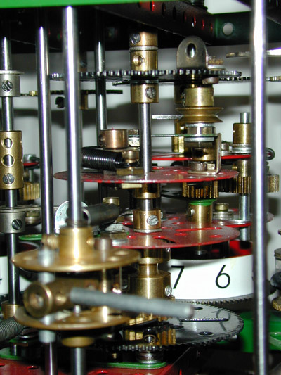
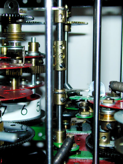
| The
view to the right shows a somewhat clearer view of the carry trip pawl
and associated mechanism. A compound rod runs from top to bottom.
The coupling is fixed only to the lower segment at each joint
and the upper rod is free to rotate in the coupling. The picture is
actually showing the lower half of one trip assembly (at the top of the
picture), and the top half of another trip assembly (in the lower part
of the picture). At the top the position of the trip pawl can be seen
relative to the angle bracket on the trip gear. In the lower half, a
second pawl can be seen. This one retains the carry assembly against
the pull of the tension spring. When the trip pawl (on the rank below
this one) is pushed by the turn of the trip gear, the carry assembly is
released and rotates till
the narrow strip contacts the vertical rod seen to the right of the
picture.
The pawls are returned to the idle position by the lower spring
attached
to the double arm crank. Not visible in the picture is the threaded pin
mounted in the hole right behind the rod carrying the crank which
provides the stop to position the pawls in the idle condition. As the carry axis subsequently rotates, the 2" rod pushes against the pulley returning the assembly to the idle position and carrying the 2½" gear with it. Since this gear is in mesh with the gear on the digit wheel, the digit wheel is advanced one unit. If in advancing, the digit wheel passes from 9 to 0, the carry assembly on the rank above will be tripped to propagate a carry to the next more significant digit. |
 |
must be propagated sequentially from digit to digit up the column. To achieve this the carry arms are arranged spirally on the carry axes. In order to get the carry operation completed in one turn of the main crank, the carry axes must revolve more quickly than they would if only making one turn per full cycle of the machine. On every other rotation of the carry axis, since no addition has preceded it, there naturally are no carries to propagate and the carry axis rotates with no action resulting.
This is in fact one aspect of the machine that would not scale up directly to numbers of arbitrary numbers of digits. Babbage recognized this in his original plans and to accommodate the time required for the carry propagation he also staggered the digit by digit addition up the columns, which had the desirable side effect that the load on the drive is more uniform. However, for this very small scale model which does not handle large enough numbers for this to be an issue, I preferred the simplicity of having all the digits be added simultaneously, which makes setup and alignment of the machine much simpler.
Framework
Arrangement of axes and drive system
Decimal digit storage
Digit readout and addition
> Carry detection and propagation
Setup and adjustment
Operation
Parts list
Last modified: 16 July 2004 If you experience any problems with this site, please contact the webmaster |
©
2003, 2004 Tim Robinson |