Decimal
Counter
Decimal counters have long been considered a challenge in Meccano because of the lack of any part with obvious five-fold or ten-fold symmetry. John Westwood has suggested that the range should have been extended to include a 10 hole bush wheel, and a number of the replica parts manufacturers have obliged. However, it turns out there is a very effective way of building a decimal counter using only standard Binns Rd. parts. I first built decimal counters a few years ago for use on a differential analyzer for recording shaft rotations. A recent discussion on Spanner prompted me to think about this problem anew, and as often happens, I was able to come up with an improved design that uses fewer parts and is more pleasing in appearance.

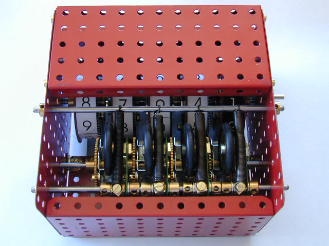
Top view of the finished unit
The example described here operates as does the odometer in a car. The right most dial indicates tenths of a rotation of the input shaft and turns continuously with the input. The remaining dials move in discrete steps whenever the dial to the right changes from 9 to 0 (or vice versa). The counter can fairly easily be preset to any value by manually turning the dials and it can count up or down. While this example has a total of five dials, and so can count to 9999.9 there is no reason in principle this range cannot be increased (though beyond some point there will be too much load presented to the input when all the dials have to change simultaneously), and of course it can easily be reduced.
The key observation, which makes this
compact design
possible, is that a 95t gear can be meshed directly with a 57t gear to
provide
a ratio of 5:3. This means that one tenth
of a revolution of the 95t gear corresponds to one sixth
of a revolution of the 57t gear, so that we can hold the 95t gear in on
of ten
discrete positions by instead holding the 57t gear in one of six
discrete
positions. This is easily accomplished
using a six hole wheel disc with six double brackets bolted to it. A diametrically opposite pair of these is
then bolted to the 57t gear (boss in, with washers as spacers to
prevent teeth
fouling on the lugs of the double brackets). It
is important the assembly runs freely on a rod. A
roller consisting of a 1” pulley with
rubber ring mounted on a pivot bolt in the end hole of a crank provides
the
detent, light pressure being applied by a tension spring (be sure to
pick
cranks with the tapped bore at right angles to the arm of the crank). Four of these assemblies are needed for a 5
digit counter.
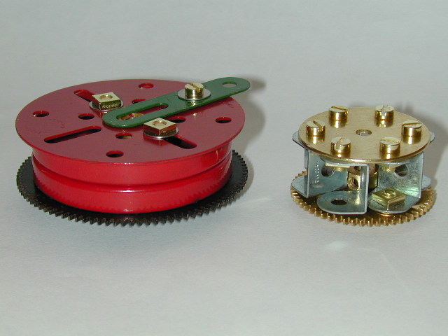
The principal sub-assemblies
Bottom view of the finished unit
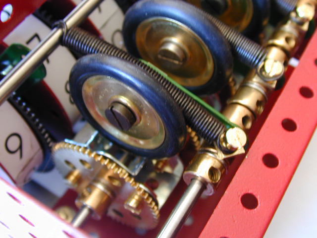
Detent Assembly Detail
PARTS REQUIRED:
| Part
Number |
Description |
Qty. |
|---|---|---|
| 2a |
Perforated strip, 4½" | 2 |
| 11 |
Double bracket, ½" x ½" | 24 |
| 12 |
Angle bracket, ½" x ½" | 2 |
| 14 |
Axle rod, 6½" | 4 |
| 22 |
Pulley, 1" | 4 |
| 24c |
Wheel disc 6 hole, 1 3/8" | 4 |
| 27a |
Gear wheel 57 teeth, 1½" | 4 |
| 27c |
Gear wheel 95 teeth, 2½" | 4 |
| 37a |
Nut | 86 |
| 37b |
Bolt, 7/32" | 68 |
| 38 |
Washer, 3/8" | 23 |
| 43 |
Tension spring | 4 |
| 52 |
Flanged plate, 5½"x 2½" | 3 |
| 52a |
Flat plate, ½" x 3½" | 2 |
| 55a |
Slotted strip, 2" | 4 |
| 59 |
Collar | 42 |
| 62 |
Crank | 4 |
| 69 |
Set screw | 1 |
| 69a |
Grub screw, 5/32" | 19 |
| 70 |
Flat plate, 5½" x 2½" | 1 |
| 109 |
Face plate, 2½" | 6 |
| 111 |
Bolt, ¾" | 10 |
| 137 | Wheel flange | 10 |
| 147b |
Pivot bolt | 4 |
| 155 |
Rubber ring, 1" | 4 |
| 525 |
Core holder for rectangular coil | 10 |
| 561 |
Thin washer (mostly finish protection) | 80 |
Click here to download the parts list in MeccInv format.
Last modified: 12 February 2007 If you experience any problems with this site, please contact the webmaster |
©
2004-2007 Tim Robinson |